Always pay attention to the status bar at he bottom of your Inkscape window. It will tell you exactly what type of object you are working on i.e. Rectangle, Circle, Text, Offset or Path.
Don’t bother setting the size of your document. When we output to a vinyl cutter only the raw polygon data will be sent. I deliberately zoom out a bit and start drawing my shapes completely outside the document boundaries. The document properties do not matter(!)
Step 1 – Prepare content for vinyl cutting
Download the STARWARS font
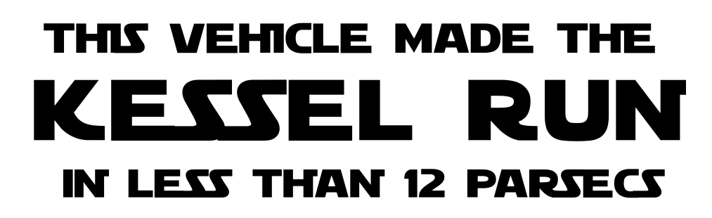
Create 3 Text Objects:
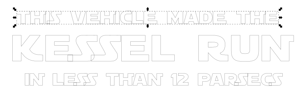
“This vehicle made the”
“Kessel Run”
“in less than 12 parsecs”
Use capital characters.
Change the font size for “Kessel Run” to a larger size.
The exact absolute size of your text or document does not matter as vector content can be scaled up or down to the output size you want.
I would attempt to always scale proportionally by holding CTRL to maintain aspect ratio.
Change the spacing between letters if you want to ‘stretch’ the text without deforming.
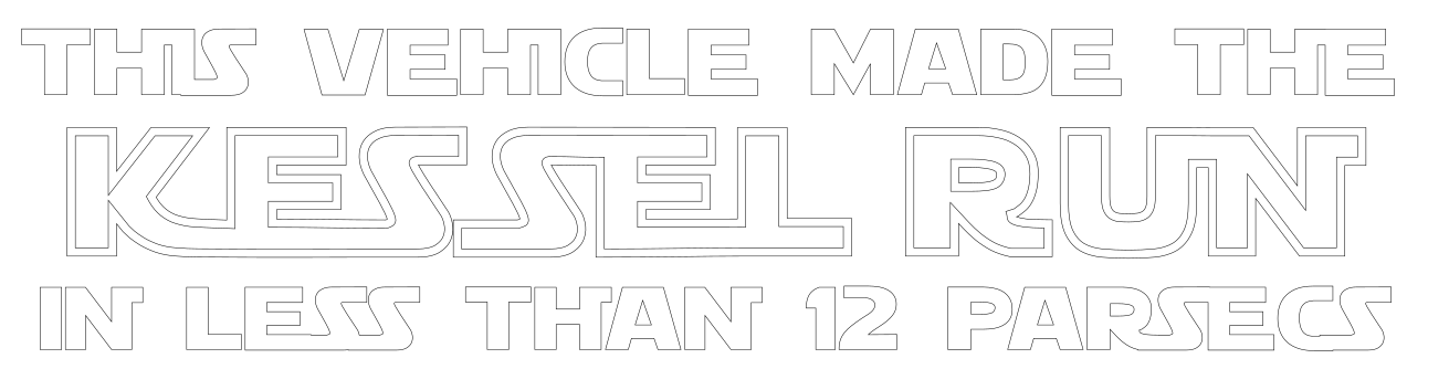
This is how all content needs to be prepared for Vinyl Cutter plotting:
Edit> Select All (or use [CTRL]+[A])
Path > Object To Path
Fill > None
Stroke Path > Black
Stroke Style > 1px
Vinyl Cutters cut lines in PVC vinyl material. The rotating knife only sticks out one tenth of a millimeter so it cuts the vinyl but not the backing. Always perform a test plot using a simple single shape first when changing media. When using rolls of PVC vinyl, the image on your screen will come out of the vinyl cutter sideways; if you unroll a large roll of PVC vinyl 9 meter by 60cm it basically is an extremely wide piece of paper in landscape orientation. What you see on your monitor screen is also in landscape orientation. You can add content to the right hand side as much as you like, towards the bottom not so much. The document boundaries Inkscape uses for normal printing do not apply as the plot extension only sends shape object coordinates to the vinyl cutter.
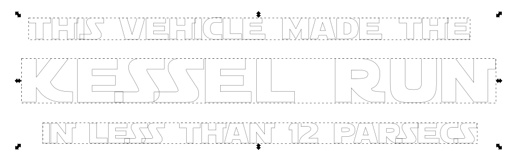
Now that we have all objects collapsed to plain shapes (Path objects) you will notice some text appears overlapped. This is because each letter is a closed polygon.
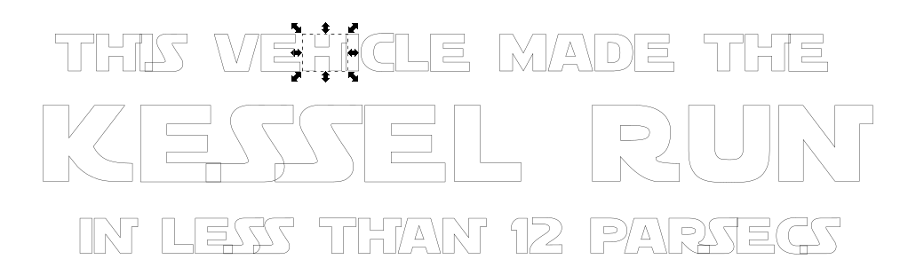
Step 2 – Clean up overlapping text
Let’s clean up the overlapping text.
Select 1 object
Path > Union
It doesn’t work because letters in Text Objects converted to Paths are grouped.
You can do 2 things:
a. Maintain the group and simply double click to enter a group and continue work from inside the group. Simply double click in an empty area outside the group to exit. Note that The ESC key does not exit the group. Note that if you double click a single shape again, you will enter “Edit Paths by Nodes” mode. This behavior is standard for editing plain Path objects.
b. Ungroup the object. Note that you have to convert to Path first;
Note that the original Text Object was not grouped – if you double click a Text Object you can change the text using your keyboard but nothing else.
2a. Object Ungrouping
Select an object
Object > Ungroup
(or double click to enter the group if you want to experiment with using groups)
Each individual letter is now selectable as a single object.
Repeat for the remaining 2 objects
2b. Combining Path Objects
Select all individual letters of a single line of text.
Path > Combine
The polygons of each individual Path object are joined into a single Path object consisting of multiple closed polygons.
Repeat for the remaining 2 objects.
2c. ‘Fusing’ the overlapping closed polygons of a single Path Object (= ‘Union’)
Select an object
Path > Union
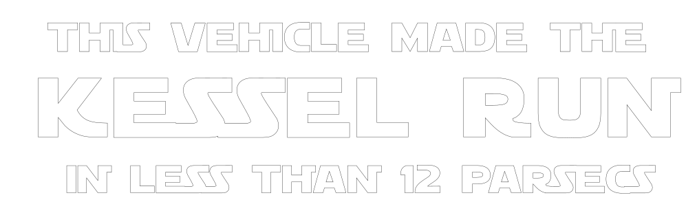
The overlapping polygons are now fused together.
Step 3 – Plot to Vinyl cutter
You can now already plot to the vinyl cutter if you like:
Extensions > Export > Plot.
Check the COM port and press Apply or OK.
Pressing Apply leaves the dialog window open for a next plot. Pressing OK closes the dialog window.
3a. Checking the size before you plot to the vinyl cutter
Select All.
File > Export PNG Image
In the Export PNG Image dialog window on the side of your Inkscape window, select the “Selection” tab and change the Units to “cm”.
Width and Height will tell you what size on paper to expect.
(click image to enlarge)
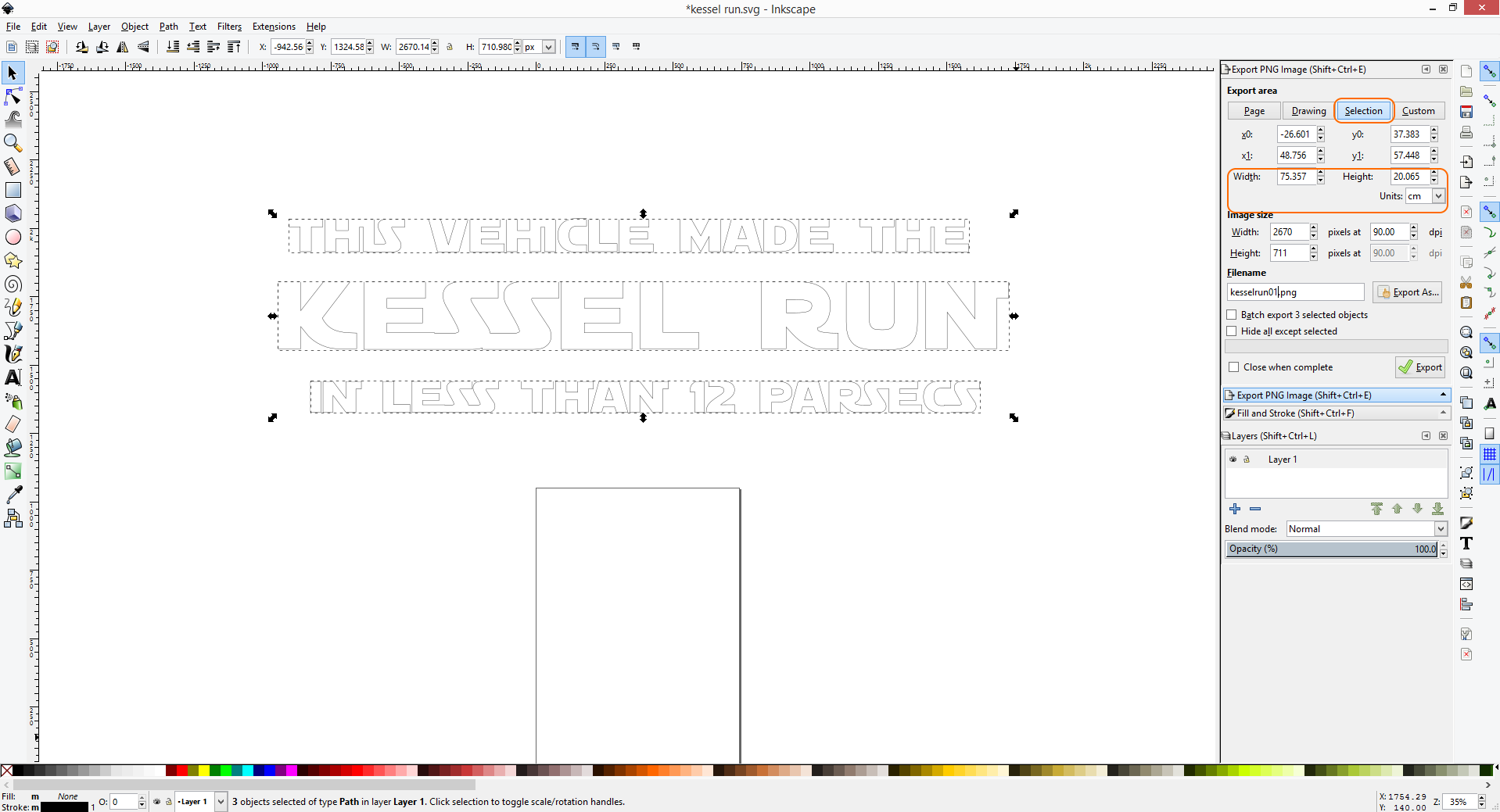
Simply resize your selection by moving the handles (hold CTRL to maintain aspect ratio!) and watch the numbers change.
Alternatively enter the desired dimensions in the ‘Image Size’ fields of the Export PNG Image dialog window to resize your content.
Step 4 – Edit Paths
If you look at some of these stickers for sale on the internet you will notice some of the letters are actually joined together:
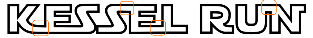
Suppose we want to join the letter K and letter E in our document.
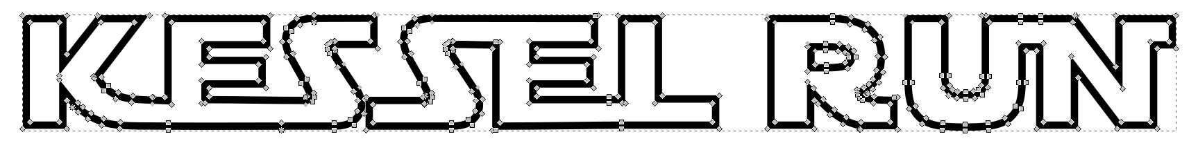
If we double click our ‘KESSEL RUN’ path object we can change to Edit Paths by Node mode.
Editing paths is complex and best demonstrated face-to-face. In a nutshel, you can move nodes and change their Bezier handles. A node can be set to act as a sharp corner node, or a smooth curve node, or a bit of both. The buttons in the toolbar change how nodes behave.
No matter how hard you try, it is not possible to join the two closed polygons together.
We will need to introduce an extra polygon to bridge the area and then use the union option to fuse them together.
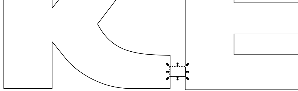
Draw a rectangle. It doesn’t really matter if there is a stroke or fill color. Just make sure it ‘touches’ both shapes and does not overlap too much.
Select both the ‘KESSEL RUN’ Path Object and the Rectangle Object. Click on the first object to select it. Hold down SHIFT. Click on the second object to select it.
Path > Union
If you accidentally used a color and fill in your rectangle, simply it back to our ‘vinyl cutter’ preferred settings:
Fill > None
Stroke Path > Black
Stroke Style > 1px
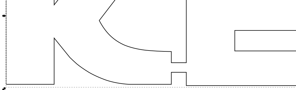
And we are back where we were before, but now the two separate closed polygons of the letter K and letter E are connected into a single closed polygon ‘KE’. If you were to apply a fill color, you would see the two letters are now fused together as one.
You can double click to delete unwanted nodes and move Bezier handles of individual nodes to smoothen the area connecting the letters together.
For nodes not directly connected to nodes in sharp corners, find and use the “Make selected nodes auto smooth” button in the toolbar to bring order to the chaos if Bezier handles are giving you a hard time. It sets the Bezier handle angles automatically for a smooth transition.
For all other nodes, make sure a node is set to the correct node type (corner, smooth or symmetric). Then move the Bezier handles. You can hold [CTRL] for angle snap. You can [CTRL] + double click a Bezier handle endpoint to change a symmetric node to a smooth node to a corner node automatically.
Try it (!) – Draw a rectangle, convert it to a Path Object and double click to edit. Change a corner node to a symmetric node and move the Bezier handles. Hold [CTRL] and drag the Bezier handle. Now [CTRL]+double click and move the Bezier handle again. Do the same with the other Bezier handle. Note how the node symbol changes from a square (symmetric/smooth node type) to a diamond (corner node type). Magic!
Edit Paths – joining two closed splines the proper way
Here is another method for joining the two closed splines of the letters K and E in ‘KESSEL’.
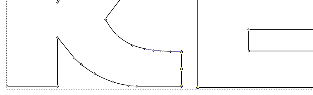
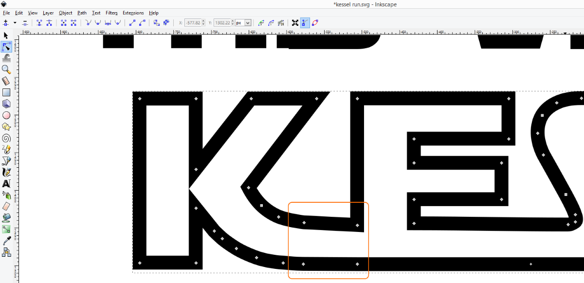
First, we select two corner nodes of the letter K and select [Delete segment between two non-endpoint nodes].
Repeat this same step for the letter E.
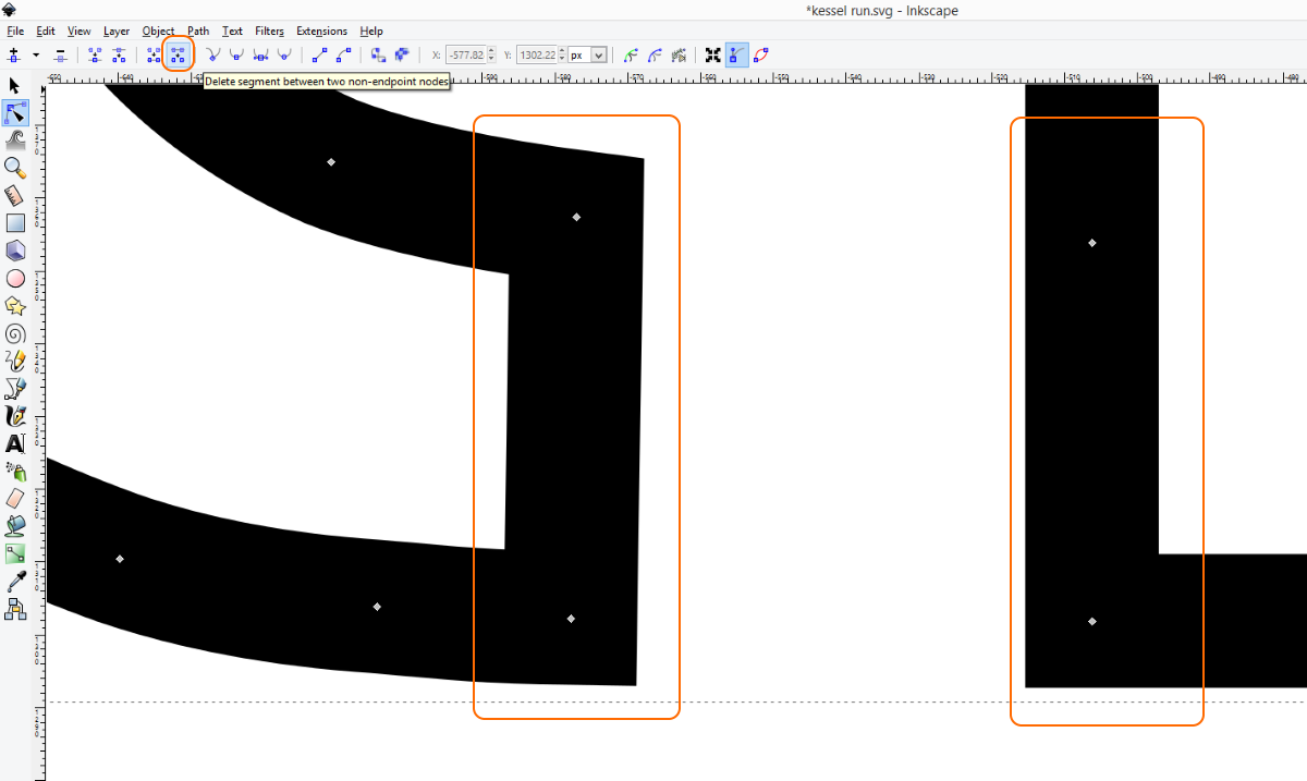
The two closed splines are now open splines ready for joining.
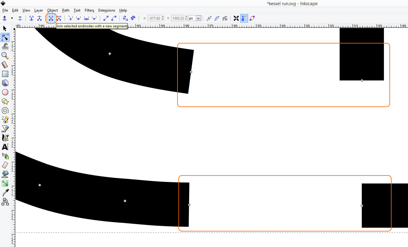
Select the top two nodes as seen in the picture below and press [Join selected endnodes with a new segment] button to bridge the gap.
Repeat this same step for the bottom two nodes.
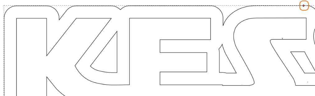
The letters K and E in ‘KESSEL’ are now joined.
Step 5. Outline Text
Select the ‘KESSEL RUN’ Path Object.
Edit >Copy
Edit > Paste in place
Path > Linked Offset
Drag the handle outward to create the desired radius.
You most likely will find that your ‘KESSEL RUN’ Path Object outline lacks detail. No matter what you try, the outline looks like a balloon as it if was used for a chewing gum advertisement.
Also the sharp corners will now look rounded.
If you try dragging the handle to make an insert, you may have similar problems.
As we can no longer edit the original text and change the spacing of the characters, it is best to create your offset early in the process.
Please undo your linked offset steps and continue reading.
5a. A different way to create outline text
This technique preserves the stroke width of either a Text Object or Path Object – it doesn’t matter what type of object you have.
Create a Text Object “KESSEL RUN” or use your existing “KESSEL RUN” Path Object.
Fill > None
Stroke Path > Black
Stroke Style > 20px
Use the stroke width to create the desired text outline. Notice the sharp corners.
Collapse the Text Object to a Path Object if need be.
Double click to edit.
Notice how the nodes are just a single stroke using a 20px ‘thick ‘ pencil line as it were ? (click pictures to enlarge)
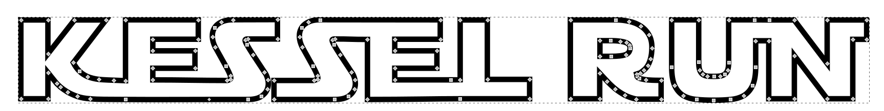
Path > Stroke to Path
The stroke width is translated into a Path Object. Notice how the nodes are now different. The letters now have “thickness” using path nodes rather than stroke width. (click pictures to enlarge)
Let’s apply our Vinyl Cutter plotting settings:
Fill > None
Stroke Path > Black
Stroke Style > 1px
We now have a document ready for vinyl cutter plotting:
Using this technique you no longer have to keep a copy of your original document before collapsing Text Objects to Path Objects. You can use any type of object and just play with the stroke width value. When you are happy with the result collapse Stroke (width) to Path Object.
You can simply select any object and use Copy and Paste In Place to create multiple layers of outlines. You can choose whether to use Stroke Width or Linked Offset (with rounded corners) as you see fit.
Tip: Draw a rectangle around your artwork and collapse to a 1px Path Object before plotting on a vinyl cutter. This makes it easier to cut out the sticker and helps when picking or weeding your sticker.
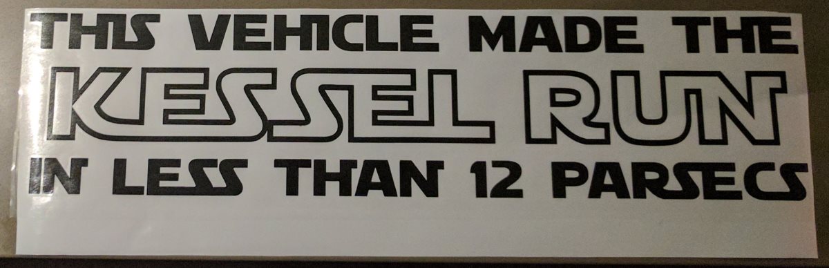
Final result
This is the final result after weeding/picking and applying medium tack application tape: