Symptoms
Hard disk had been connected to a new modular power supply but the old modular power supply’s SATA power cables were reused.
Cause
Modular power supply leads are not standardized unfortunately. If you buy a Thermaltake modular power supply to replace a Seasonic modular power supply, you have to install the Thermaltake SATA power cables as well, otherwise you risk supplying +7Vdc or +12Vdc to the GND pins of the hard disk, or +12Vdc to the +7Vdc pin of the hard disk.
Solution
A thorough step by step investigation is required to troubleshoot the faulty hard disk and attempt data recovery.
The hard disk was a 3.5 inch 1.5TB 7200RPM Western Digital Caviar Blue hard disk.
A hard disk consists of:
- Read/write head(s)
- Read/write head arm coils (electromagnet)
- Read/write head arm static magnets
- Spindle Motor
- One or more platters
- Controller board
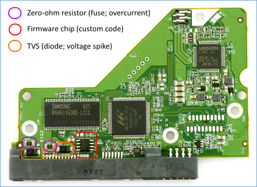
The hard disk controller board of a 3.5 inch 1.5TB 7200RPM Western Digital Caviar Blue hard disk looks like this:
Over-current protection (zero-ohm resistor)
A hard disk is protected from over-current by one or more fusible links (i.e. series inductor, fuse, polyswitch, or zero-ohm resistor). The fusible link could be as simple as a very narrow trace on the circuit board. A fusible link acts like a fuse. In normal operation the fuse will conduct current (near zero ohm resistance, effectively a short). If current consumption exceeds nominal levels, the fusible link will overheat and melt (infinite ohm resistance, effectively an open connection) protecting the sensitive electronics on the board and spindle motor and head coils. Some fusible links can recover, but most do not. Zero-ohm resistors do not self-repair and will need to be checked with a multi-meter for resistance and replaced. You can replace a faulty resistor with a bit of solder but this is not recommended as this no longer provides protection against future over-current conditions.
Over-voltage protection (transient voltage suppression)
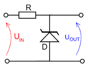
A hard disk is protected from over-voltage by one or more transient voltage suppression (TVS) diodes. A TVS diode will be connected directly across a supply rail (+5V to GND or +12V to GND), sometimes with a series inductor, fuse, polyswitch, or zero-ohm resistor. TVS diodes keep the voltage differential constant at all times and suppress voltage spikes by providing a conductive path to ground for any over-voltage situation. TVS diodes act similar to Zener diodes (also known as ‘breakdown’ diodes) used in reverse-bias condition. TVS diodes are different from normal Zener diodes in that they need to have a fast response time.
Zener diodes in reverse-bias condition
As soon as a voltage is applied across the zener diode that exceeds the rated voltage of the device, the diode’s breakdown voltage is reached at which point a process called Avalanche Breakdown occurs in the semiconductor depletion layer and a current starts to flow through the diode to limit this increase in voltage. The point at which the zener voltage triggers the current to flow through the diode can be very accurately controlled (to less than 1% tolerance) in the doping stage of the diodes semiconductor construction giving the diode a specific zener breakdown voltage.
TVS diodes do not self-repair and will need to be checked with a multi-meter for resistance and replaced. A TVS diode can be tested on the diode test range of a digital multimeter. In normal conditions it will have a low resistance in the forward direction, and a high resistance in the reverse direction. However, an in-circuit test will be complicated by the fact that the diode is connected directly across a supply rail. This means that the meter will be measuring the resistance of everything connected to that supply rail. In reality, all we are interested in is whether the diode is shorted or not, so I would suggest that the 200 ohms range could be used in preference to the diode test. On this range the meter outputs a lower test current at a lower test voltage, which means that its reading is less likely to be affected by nearby devices. If the meter reads close to zero ohms in both directions, then the diode is most probably bad. There could be a shorted component elsewhere on the circuit board, but you won’t know this until you eliminate the most likely suspect first i.e. the TVS diode.
You can simply remove a faulty TVS diode to resume normal operations but this is not recommended as this no longer provides protection against future over-voltage conditions.
Connect to power supply
Rather than measuring resistance it is also possible to connect the faulty hard disk to a power supply and measure the voltage over the fusible links and TVS diodes. For a fusible link you should measure the same voltage at either end. For a TVS diode you should measure zero volt at one end and +7Vdc or +12Vdc on the other end, depending what voltage rail it is connected to.
Swapping controller boards
With modern hard disks it is no longer possible to just swap the controller board for an identical one from a donor drive. A hard disk contains a non-volatile random access memory (NVRAM) chip with code that is unique to the hard disk. You will have to desolder this chip using a heat gun and transfer it to the donor controller board for this to work (or reprogram the chip on the replacement board).
Swapping platters
It is possible to not just swap the controller board, but to swap the platter(s) as well. This is useful in situations where the spindle motor and/or read/write heads of the original hard disk are damaged. Note that the hard disk controller board ROM chip will need to be swapped across as well still. For this operation to be successful the stack of platters needs to be kept aligned vertically perfectly whilst transferring across. Any misalignment of just a fraction of a millimeter will result in data loss without a chance of recovery. Dust-free cleanroom facilities are a must. This operation has a high chance of failure if not performed properly.
In this particular case hard disk data recovery was successful by removing a failed TVS diode and immediately copying data onto a new hard disk.


